GATE 2015 EC – Question 21
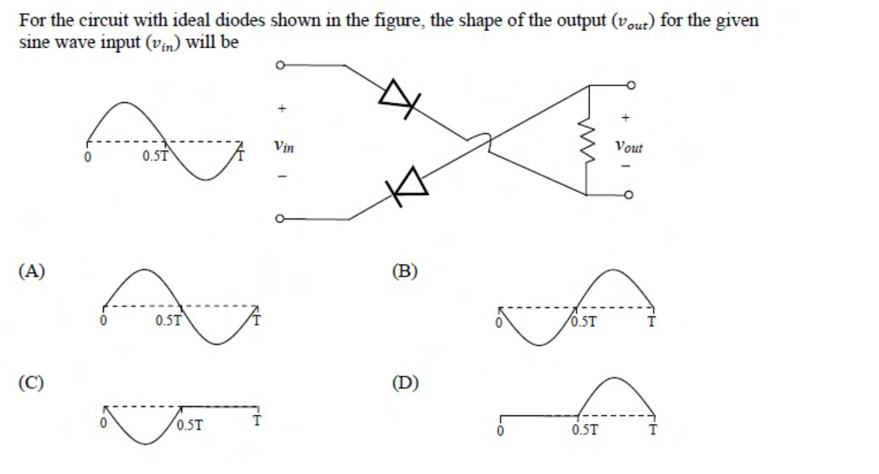
For the circuit with ideal diodes shown in the figure, the shape of the output ($v_{out}$) for the given sine wave input ($v_{in}$) will be
Practise this question in The GATE Grind →
Show answer and explanation
Correct answer: (C) Waveform (C): only the negative half-cycle
Explanation
The two ideal diodes are in series with the load, so either both conduct, which happens during one half-cycle of the input, or both are off. The cross-over wires connect the load the opposite way round, so while the diodes conduct the load voltage is $-v_{in}$, and it is zero during the other half-cycle.
The output is therefore the negative half-cycle only, with zero for the rest of the period, which is waveform (C).