Analog Circuits · Diode Circuits · 1 mark · Multiple choice
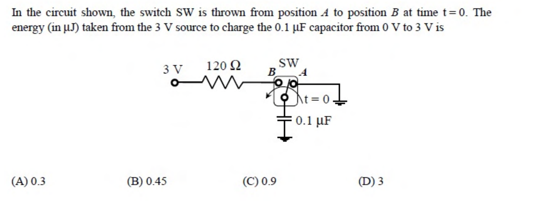
In the circuit shown, the switch SW is thrown from position A to position B at time $t = 0$. The energy (in $\mu$J) taken from the 3 V source to charge the 0.1 $\mu$F capacitor from 0 V to 3 V is
Charging a capacitor from a constant source through a resistor draws the charge $Q = CV$ from the source at voltage $V$. The energy from the source is $QV = CV^2 = 0.1\ \mu\text{F} \times 9 = 0.9\ \mu$J. Half of this is stored in the capacitor and half is lost in the resistor.
More Diode Circuits questions
GATE 2014 EC (EC1) Q19– In the circuit, PN diode D₁ has forward drop 0.7 V and Schottky diode D₂ has forward drop…
GATE 2014 EC (EC2) Q47– The diode shown has V on = 0.7 V and is otherwise ideal. If Vi = 5 sin(ωt) V, find minimum…
GATE 2014 EC (EC3) Q23– The half-wave rectifier shown uses an ideal diode. Find approximate average steady-state…
GATE 2014 EC (EC4) Q22– Two silicon diodes with forward drop 0.7 V form the circuit shown. Find the input-voltage…
GATE 2017 EC (EC2) Q22– The output V o of the diode circuit shown is connected to an averaging DC voltmeter. The…
GATE 2017 EC (EC2) Q23– In the figure, D 1 is a real silicon pn-junction diode with a 0.7 V forward drop and D 2…