GATE 2017 EC (EC2) – Question 23
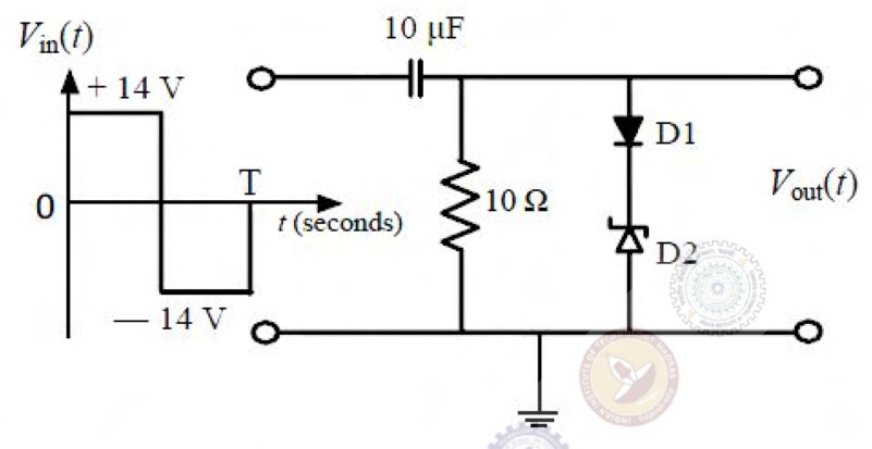
In the figure, $D_1$ is a real silicon pn-junction diode with a 0.7 V forward drop and $D_2$ is a Zener diode with breakdown voltage −6.8 V. The input $V_{in}(t)$ is a periodic square wave of period $T$, with levels +14 V and −14 V as shown.
Assuming $10\tau\ll T$, where $\tau$ is the circuit time constant, the maximum and minimum values of the output waveform are, respectively,
Practise this question in The GATE Grind →
Show answer and explanation
Correct answer: (A) 7.5 V and −20.5 V
Explanation
The conducting diode–Zener branch limits the positive output to $0.7+6.8=7.5$ V.
Under the capacitor charge-holding clamper approximation used by the key, the 28 V input swing is retained at the output. Its lower level is then $7.5-28=-20.5$ V. This gives the official answer **A**.
**Source qualification:** the printed condition $10\tau\ll T$ implies rapid discharge through the resistor, whereas the usual charge-holding approximation requires a long time constant relative to the waveform period. The original inequality is preserved; the keyed pair should not be presented as a consequence of that inequality without this qualification.