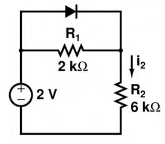
First test the diode-off state. The resistors then form a 2 kΩ+6 kΩ series circuit across 2 V. Its current is $2/8000=0.25$ mA.
The voltage across the 2 kΩ resistor, and hence the diode, is $0.25\cdot2=0.5$ V. This is below the 0.7 V turn-on voltage, so the off assumption is consistent. Thus **$i_2=0.25$ mA**.
More Diode Circuits questions
GATE 2016 EC (EC2) Q49– A half-wave rectifier has a 475\ F filter capacitor and a constant 1 A load. The figure…
GATE 2016 EC (EC3) Q23– D1 and D2 are ideal, and the two capacitors are identical. RC is much greater than the ac…
GATE 2016 EC (EC3) Q49– The Zener I–V curves are shown in Figure I and their series circuit in Figure II. As the…
GATE 2026 EC Q65– Consider the ideal diodes D1 and D2 as shown in the Figure with cut-in voltage V =0 Volt…
GATE 2025 EC Q57– All the diodes in the circuit given below are ideal. Which of the following plots is/are…
GATE 2025 EC Q61– The diode in the circuit shown below is ideal. The input voltage (in Volts) is given by V…