Analog Circuits · Diode Circuits · 2 marks · Numerical answer
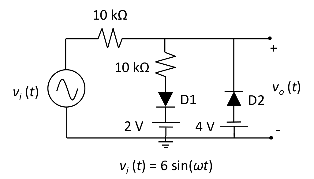
Consider the ideal diodes D1 and D2 as shown in the Figure with cut-in voltage $V_\gamma=0$ Volt and $v_i(t)$ is in Volt. The maximum voltage (Volt) of the output $v_o(t)$ is ________. (rounded off to two decimal places)
Battery polarity from the symbols: the long (positive) plate of the 2 V battery is on top, so D1 conducts once $v_o$ exceeds 2 V; the 4 V battery has its positive plate at ground, so D2 conducts only when $v_o<-4$ V. For $v_i>2$ V, D1 is on and $(v_i-v_o)/10\text{ k}=(v_o-2)/10\text{ k}$, so $v_o=(v_i+2)/2$. At the peak $v_i=6$ V the output maximum is $(6+2)/2=4.00$ V.
More Diode Circuits questions
GATE 2025 EC Q57– All the diodes in the circuit given below are ideal. Which of the following plots is/are…
GATE 2025 EC Q61– The diode in the circuit shown below is ideal. The input voltage (in Volts) is given by V…
GATE 2024 EC Q23– In the circuit shown, the n:1 step-down transformer and the diodes are ideal. The diodes…
GATE 2024 EC Q35– As shown in the circuit, the initial voltage across the capacitor is 10 V, with the switch…
GATE 2023 EC Q40– In the circuit shown below, D 1 and D 2 are silicon diodes with cut-in voltage of 0.7 V. V…
GATE 2022 EC Q57– A circuit and the characteristics of the diode (D) in it are shown. The ratio of the…