Analog Circuits · Diode Circuits · 1 mark · Numerical answer
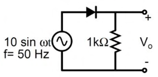
The output $V_o$ of the diode circuit shown is connected to an averaging DC voltmeter. The input is $10\sin\omega t$ V at 50 Hz. Neglecting the voltage drop across the diode, the DC voltmeter reading (in volts) is ________.
The diode conducts on the positive half-cycle and blocks the negative half-cycle. Thus the output is a half-wave rectified sine with peak 10 V.
The average over a complete cycle is $$V_{DC}=\frac1{2\pi}\int_0^\pi10\sin\theta\,d\theta=\frac{10}{\pi}.$$ This is **3.1831 V**, within the official interval 3.15–3.21 V. A DC averaging meter reads this mean, rather than the rms value.
More Diode Circuits questions
GATE 2017 EC (EC2) Q23– In the figure, D 1 is a real silicon pn-junction diode with a 0.7 V forward drop and D 2…
GATE 2016 EC (EC2) Q23– The diode in the figure has V on=0.7 V but is otherwise ideal. The magnitude of current i…
GATE 2016 EC (EC2) Q49– A half-wave rectifier has a 475\ F filter capacitor and a constant 1 A load. The figure…
GATE 2016 EC (EC3) Q23– D1 and D2 are ideal, and the two capacitors are identical. RC is much greater than the ac…
GATE 2016 EC (EC3) Q49– The Zener I–V curves are shown in Figure I and their series circuit in Figure II. As the…
GATE 2026 EC Q65– Consider the ideal diodes D1 and D2 as shown in the Figure with cut-in voltage V =0 Volt…