Analog Circuits · Diode Circuits · 2 marks · Numerical answer
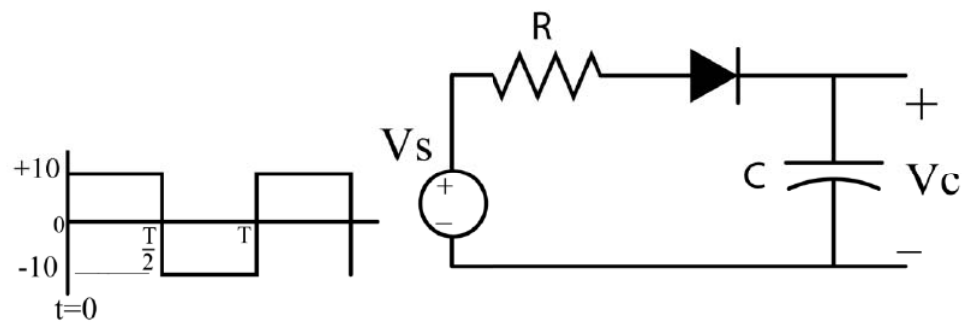
In the circuit shown, $V_s$ is a 10 V square wave of period $T=4$ ms with $R=500\ \Omega$ and $C=10\ \mu$F. The capacitor is initially uncharged at $t=0$, and the diode is assumed to be ideal. The voltage across the capacitor ($V_C$) at 3 ms is equal to ________ volts (rounded off to one decimal place).
For $0<t<2$ ms the source is $+10$ V and the diode conducts: $V_C=10\left(1-e^{-t/RC}\right)$ with $RC=5$ ms, so $V_C(2\text{ ms})=10(1-e^{-0.4})=3.3$ V. For $2<t<4$ ms the source is $-10$ V, the diode is reverse biased and the capacitor holds its charge, so $V_C(3\text{ ms})=3.3$ V.
More Diode Circuits questions
GATE 2018 EC Q36– The circuit shown in the figure is used to provide regulated voltage (5 V) across the 1\ k…
GATE 2015 EC Q21– For the circuit with ideal diodes shown in the figure, the shape of the output (v out) for…
GATE 2015 EC Q22– In the circuit shown below, the Zener diode is ideal and the Zener voltage is 6 V. The…
GATE 2015 EC Q23– In the circuit shown, the switch SW is thrown from position A to position B at time t = 0.…
GATE 2014 EC (EC1) Q19– In the circuit, PN diode D₁ has forward drop 0.7 V and Schottky diode D₂ has forward drop…
GATE 2014 EC (EC2) Q47– The diode shown has V on = 0.7 V and is otherwise ideal. If Vi = 5 sin(ωt) V, find minimum…