GATE 2016 EC (EC3) – Question 29
Control Systems · Transfer Function, Block Diagram and Signal Flow Graph · 1 mark · Multiple choice
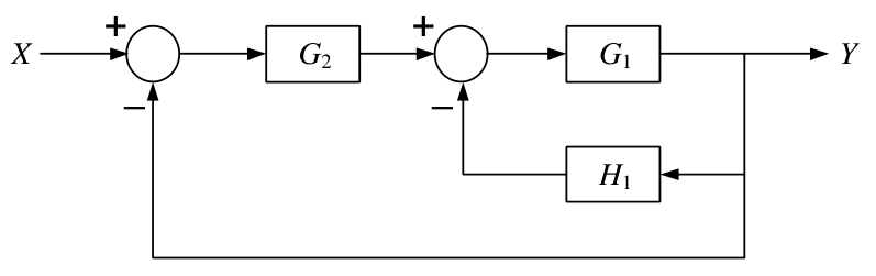
For the feedback block diagram shown, the overall closed-loop gain G is
- $G_1G_2/(1+G_1H_1)$
- $G_1G_2/(1+G_1G_2+G_1H_1)$
- $G_1G_2/(1+G_1G_2H_1)$
- $G_1G_2/(1+G_1G_2+G_1G_2H_1)$
Practise this question in The GATE Grind →
Show answer and explanation
Correct answer: (B) $G_1G_2/(1+G_1G_2+G_1H_1)$
Explanation
The first summing node gives X−Y. After G2, the second node subtracts H1Y, so the input to G1 is $G_2(X-Y)-H_1Y$.
Thus $Y=G_1G_2X-G_1G_2Y-G_1H_1Y$. Collect output terms and divide by X:
$$G=\frac{G_1G_2}{1+G_1G_2+G_1H_1}.$$
This is **B**.
More Transfer Function, Block Diagram and Signal Flow Graph questions
- GATE 2026 EC Q19 – A control system is shown in the Figure. Which option represents the correct transfer…
- GATE 2025 EC Q56 – Consider a system represented by the block diagram shown below. Which of the following…
- GATE 2023 EC Q42 – In the following block diagram, R(s) and D(s) are two inputs. The output Y(s) is expressed…
- GATE 2021 EC Q23 – The block diagram of a feedback control system is shown in the figure. The transfer…
- GATE 2019 EC Q42 – The block diagram of a system is illustrated in the figure shown, where X(s) is the input…
- GATE 2014 EC (EC2) Q31 – For the system shown, find Y(s)/X₂(s) when X₁(s) = 0.
All Transfer Function, Block Diagram and Signal Flow Graph questions →