GATE 2021 EC – Question 57
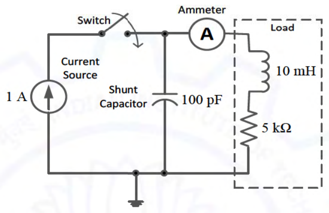
The circuit in the figure contains a current source driving a load having an inductor and a resistor in series, with a shunt capacitor across the load. The ammeter is assumed to have zero resistance. The switch is closed at time $t=0$.
Initially, when the switch is open, the capacitor is discharged and the ammeter reads zero ampere. After the switch is closed, the ammeter reading keeps fluctuating for some time till it settles to a final steady value. The maximum ammeter reading that one will observe after the switch is closed (rounded off to two decimal places) is ________ A.
Practise this question in The GATE Grind →
Show answer and explanation
Correct answer: 1.43 to 1.45
Explanation
The ammeter reads the load (inductor) current, for which $\frac{I_L(s)}{I_s(s)}=\frac{1}{LCs^2+RCs+1}$. Here $\omega_n=\frac{1}{\sqrt{LC}}=\frac{1}{\sqrt{10\text{ mH}\times100\text{ pF}}}=10^6$ rad/s and $2\zeta\omega_n=\frac RL=5\times10^5$, so $\zeta=0.25$. For a 1 A step, the peak current is $1+M_p$ with $M_p=e^{-\pi\zeta/\sqrt{1-\zeta^2}}=e^{-0.811}=0.444$, so the maximum reading is about $1.44$ A.