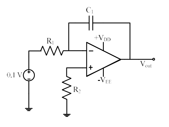
The circuit is an integrator (capacitor $C_1$ in the feedback path) fed by a constant $+0.1$ V through $R_1$ at the inverting input. The output ramps as $-\frac{0.1}{R_1C_1}t$ and, with no DC feedback, runs away until it saturates at the negative supply $-V_{EE}$.
More Operational amplifiers: characteristics and applications questions
GATE 2022 EE Q36– The output impedance of a non-ideal operational amplifier is denoted by Z out. The…
GATE 2022 EE Q44– The current gain (I out/I in) in the circuit with an ideal current amplifier given below…
GATE 2019 EE Q27– A current controlled current source (CCCS) has an input impedance of 10\ and output…
GATE 2019 EE Q44– In the circuit below, the operational amplifier is ideal. If V 1=10 mV and V 2=50 mV, the…
GATE 2018 EE Q25– The op-amp shown in the figure is ideal. The input impedance v ini in is given by
GATE 2015 EE Q17– Of the four characteristics given below, which are the major requirements for an…