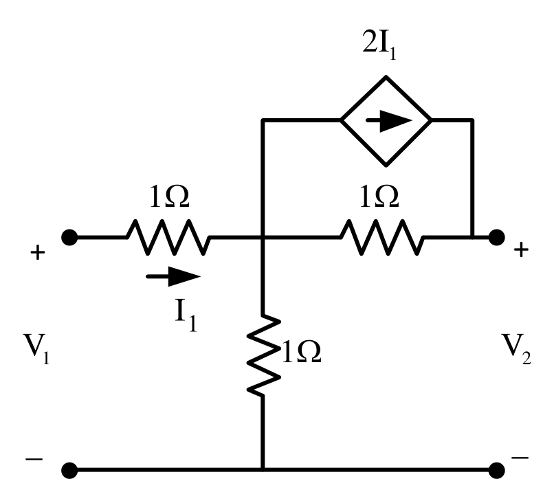
The current source $2I_1$ is connected from the input node to the output node, so with $V_2=0$ the port current is $I_{in}=I_1+2I_1=3I_1$, where $I_1$ is the current in the first $1\ \Omega$ resistor. At the middle node, $I_1=\frac{V_B}{1}+\frac{V_B-0}{1}$, so $V_B=\frac{I_1}{2}$ and $V_1=I_1+V_B=1.5I_1$. Then $h_{11}=\frac{V_1}{I_{in}}=\frac{1.5I_1}{3I_1}=0.5\ \Omega$.
More Network Elements: Ideal voltage and current sources, dependent sources, R, L, C, M elements questions
GATE 2018 EE Q42– The equivalent impedance Z eq for the infinite ladder circuit shown in the figure is Each…
GATE 2014 EE (EE1) Q16– The three elements shown form part of a circuit. Find total power absorbed (W).
GATE 2014 EE (EE1) Q39– A lamp is rated 40 W, 240 V. Its resistance at 26°C is 120 Ω and temperature coefficient…
GATE 2017 EE (EE2) Q32– The 1 F capacitor in the circuit is initially uncharged. The energy transferred from the…
GATE 2016 EE (EE2) Q47– The capacitor initially has 4 V. S1 closes at t=0. The charge lost between t=25 μs and…
GATE 2015 EE (EE2) Q28– The series RL circuit has zero initial conditions and a DC source V switched on at t=0.…