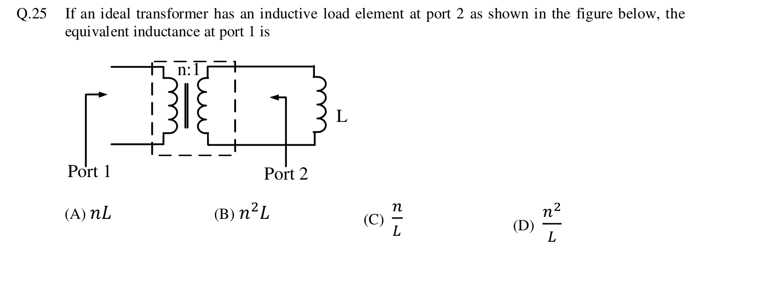
With a turns ratio of $n : 1$ between port 1 and port 2, an impedance on the secondary side appears at the primary multiplied by the square of the ratio. So the inductor $L$ looks like $n^2 L$ at port 1.
More Single phase transformer: equivalent circuit, phasor diagram, open circuit and short circuit tests, regulation and efficiency questions
GATE 2015 EE Q32– The self inductance of the primary winding of a single phase, 50 Hz, transformer is 800…
GATE 2014 EE (EE1) Q22– At specified transformer input voltage and frequency, the equivalent core radius is…
GATE 2016 EE (EE2) Q13– An ideal transformer has primary:secondary turns 1:100. The primary is driven by 100 V…
GATE 2015 EE (EE2) Q30– Choose transformer ratios a,b so Zin is purely resistive and equals 2.5 Ω at angular…
GATE 2015 EE (EE2) Q57– A three-winding transformer has N1=100,N2=N3=50 and negligible magnetizing current. With…
GATE 2026 EE Q31– A 220 V/12 V single-phase transformer is designed for use in India and rated 100 VA at 50…