GATE 2016 EE – Question 54
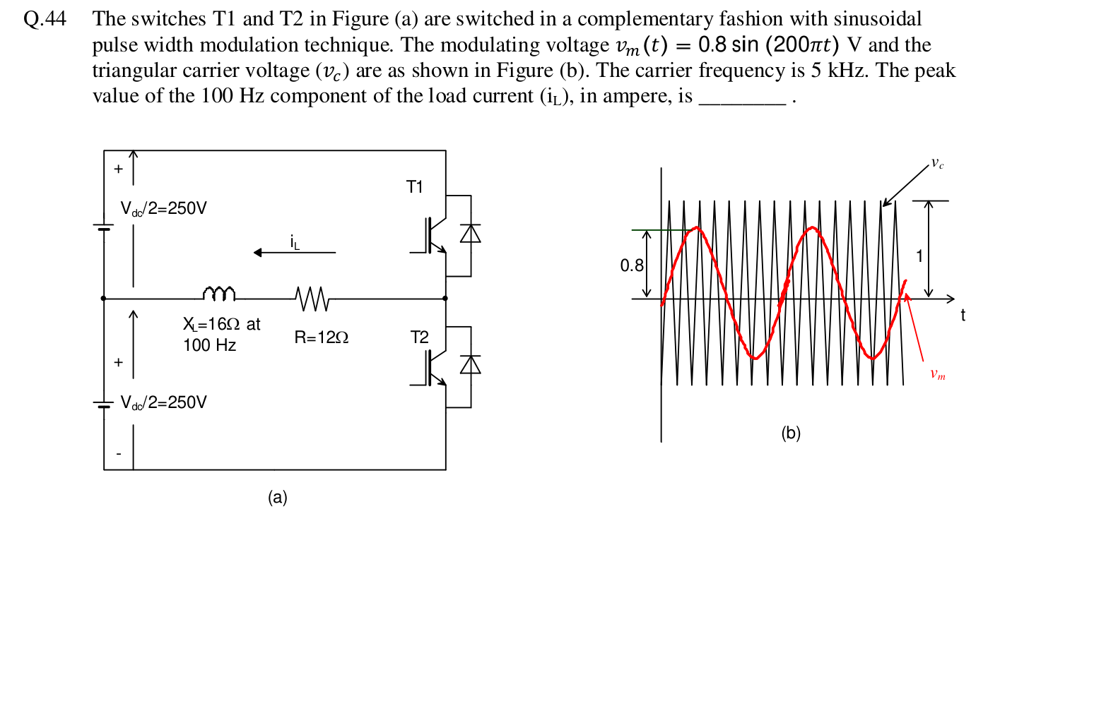
The switches T1 and T2 in Figure (a) are switched in a complementary fashion with sinusoidal pulse width modulation technique. The modulating voltage $v_m(t) = 0.8 \sin(200\pi t)$ V and the triangular carrier voltage ($v_c$) are as shown in Figure (b). The carrier frequency is 5 kHz. The peak value of the 100 Hz component of the load current ($i_L$), in ampere, is ________.
Practise this question in The GATE Grind →
Show answer and explanation
Correct answer: 9.9 to 10.1
Explanation
The modulation index is $m = 0.8$. The peak of the fundamental output voltage is $m \times \frac{V_{dc}}{2} = 0.8 \times 250 = 200$ V. The load impedance at 100 Hz is $\sqrt{12^2 + 16^2} = 20\ \Omega$, so the peak current is $\frac{200}{20} = 10$ A.