GATE 2016 EC – Question 26
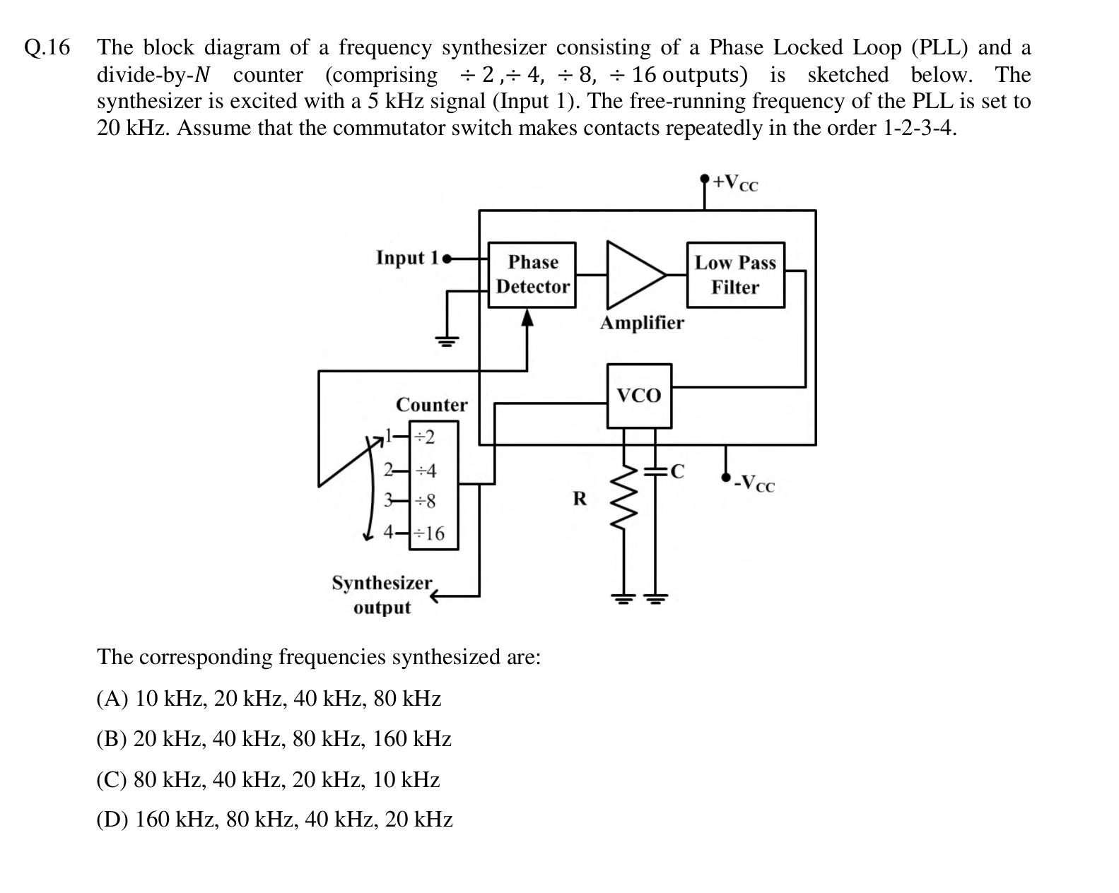
The block diagram of a frequency synthesizer consisting of a Phase Locked Loop (PLL) and a divide-by-$N$ counter (comprising $\div 2$, $\div 4$, $\div 8$, $\div 16$ outputs) is sketched below. The synthesizer is excited with a 5 kHz signal (Input 1). The free-running frequency of the PLL is set to 20 kHz. Assume that the commutator switch makes contacts repeatedly in the order 1-2-3-4.
[Figure: A PLL made of a phase detector, amplifier, low-pass filter and VCO. The VCO output goes to a counter with outputs $\div 2$, $\div 4$, $\div 8$ and $\div 16$ selected by a commutator switch (positions 1 to 4). The selected counter output is fed back to the phase detector, and the VCO output is the synthesizer output.]
The corresponding frequencies synthesized are:
Practise this question in The GATE Grind →
Show answer and explanation
Correct answer: (A) 10 kHz, 20 kHz, 40 kHz, 80 kHz
Explanation
When the loop is locked, the divided-down VCO frequency equals the 5 kHz input. So the VCO output is $5 \times N$ kHz. For the dividers $\div 2$, $\div 4$, $\div 8$ and $\div 16$ the output frequencies are 10, 20, 40 and 80 kHz.