GATE 2026 EE – Question 44
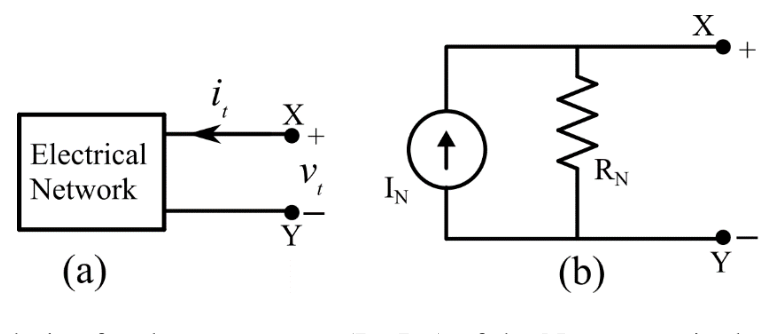
The terminal voltage and current of a linear electrical network shown in Figure (a) are given in the table.
| Terminal voltage ($v_t$) | Terminal current ($i_t$) |
|---|---|
| 18 V | −0.5 A |
| 30 V | 0.5 A |
| 36 V | 1.0 A |
The correct choice for the parameters ($I_N$, $R_N$) of the Norton equivalent circuit shown in Figure (b) is:
Practise this question in The GATE Grind →
Show answer and explanation
Correct answer: (C) $I_N=2.0$ A, $R_N=12.0\ \Omega$
Explanation
The table is linear: $\dfrac{\Delta v}{\Delta i}=\dfrac{30-18}{0.5-(-0.5)}=12\ \Omega$ and $\dfrac{36-30}{1.0-0.5}=12\ \Omega$. So the equivalent resistance is $R_N=12\ \Omega$. The open-circuit voltage (where $i_t=0$) is $24$ V, and the short-circuit magnitude is $24/12=2$ A, so $I_N=2$ A.