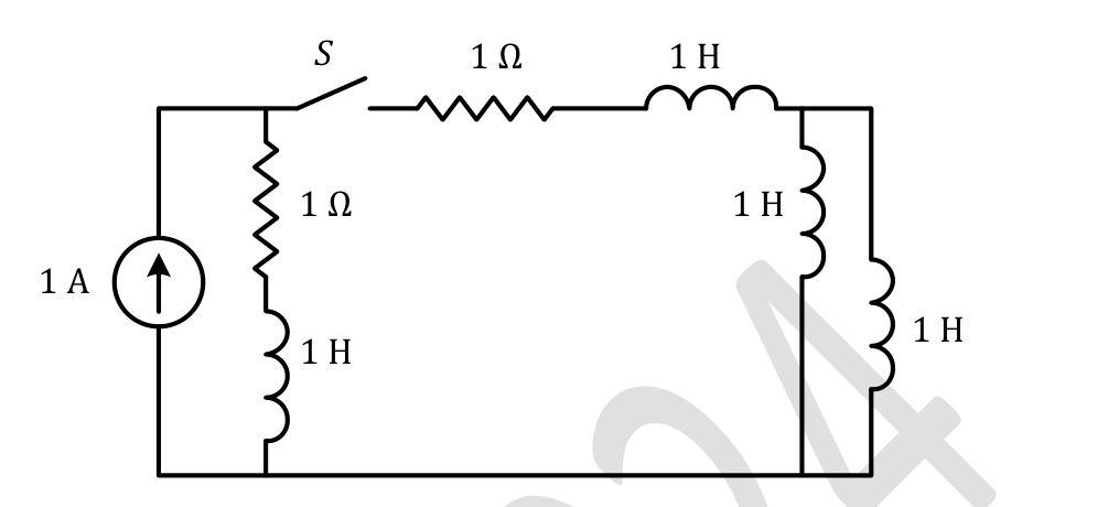
The circuit shown in the figure with the switch $S$ open, is in steady state. After the switch $S$ is closed, the time constant of the circuit in seconds is
For the time constant the ideal 1 A source is replaced by an open circuit. With S closed, the remaining circuit is a single loop containing the left (1 Ω, 1 H) branch, the (1 Ω, 1 H) branch through the switch, and the two 1 H inductors in parallel ($0.5$ H). Total $R=1+1=2\ \Omega$ and total $L=1+1+0.5=2.5$ H, so $\tau=L/R=1.25$ s.
More Transient response of DC and AC networks, sinusoidal steady-state analysis, resonance, two port networks, balanced three phase circuits, star-delta transformation, complex power and power factor in AC circuits questions
GATE 2023 EE Q29– The value of parameters of the circuit shown in the figure are R 1=2\ , R 2=2\ , R 3=3\ ,…
GATE 2023 EE Q54– The circuit shown in the figure is initially in the steady state with the switch K in open…
GATE 2022 EE Q21– In the circuit shown below, a three-phase star-connected unbalanced load is connected to a…
GATE 2022 EE Q27– An inductor having a Q-factor of 60 is connected in series with a capacitor having a…
GATE 2022 EE Q28– The network shown below has a resonant frequency of 150 kHz and a bandwidth of 600 Hz. The…
GATE 2022 EE Q34– Two balanced three-phase loads, as shown in the figure, are connected to a 1003 V,…