GATE 2024 EE – Question 18
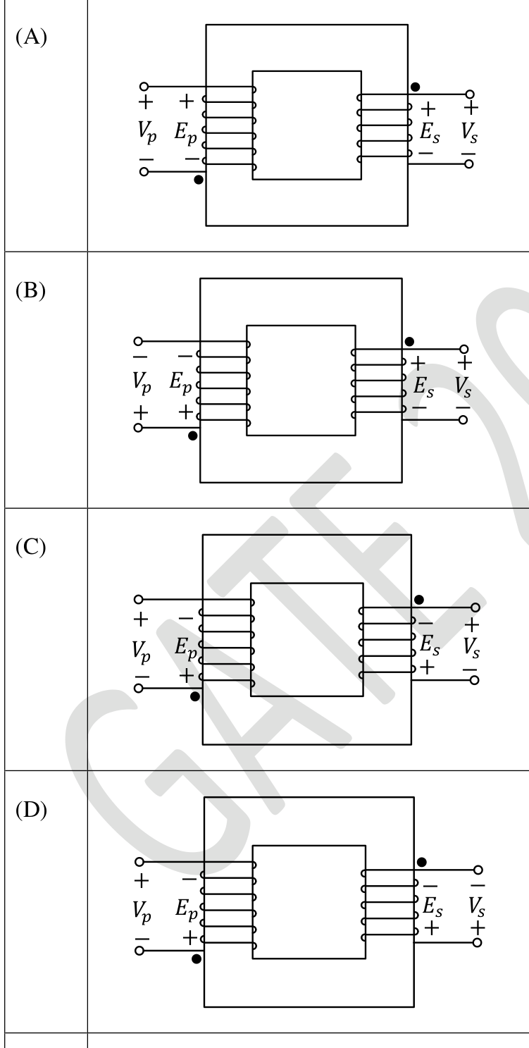
Which one of the following options represents possible voltage polarities in a single phase two winding transformer? Here, $V_p$ is the applied primary voltage, $E_p$ is the induced primary voltage, $V_s$ is the open circuit secondary voltage, and $E_s$ is the induced secondary voltage.
Practise this question in The GATE Grind →
Show answer and explanation
Correct answer: (B) Diagram (B)
Explanation
The induced voltages follow the dot convention: the dotted terminals of $E_p$ and $E_s$ have the same polarity. In addition $E_p$ has the same polarity as the applied $V_p$ (it balances it), and at open circuit $V_s=E_s$. Diagram (B) satisfies all of these: $V_p$ and $E_p$ both have $+$ at the dotted (lower) end of the primary, $E_s$ and $V_s$ both have $+$ at the dotted (upper) end of the secondary. In (A) the two dotted ends have opposite polarity, and in (C) and (D) $E_p$ is opposite to $V_p$ with $E_s$ inconsistent with the dots.