GATE 2023 EE – Question 23
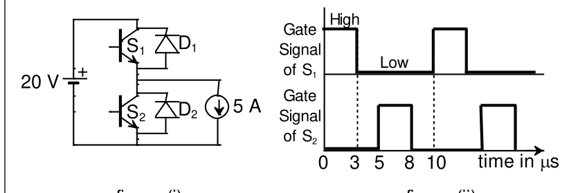
The chopper circuit shown in figure (i) feeds power to a 5 A DC constant current source. The switching frequency of the chopper is 100 kHz. All the components can be assumed to be ideal. The gate signals of switches $S_1$ and $S_2$ are shown in figure (ii). Average voltage across the 5 A current source is
Practise this question in The GATE Grind →
Show answer and explanation
Correct answer: (A) 10 V
Explanation
The 5 A current is drawn from the midpoint. It is supplied through $S_1$ when $S_1$ is on, and through the anti-parallel diode $D_2$ (from ground) whenever $S_1$ is off (including the dead times), because the source needs current flowing into the midpoint from the top or from ground. So the midpoint voltage is 20 V while $S_1$ is on and 0 V otherwise. $S_1$ conducts for $3+2=5\ \mu$s of each 10 μs period, so the average voltage is $20\times0.5=10$ V.