GATE 2017 EC (EC2) – Question 25
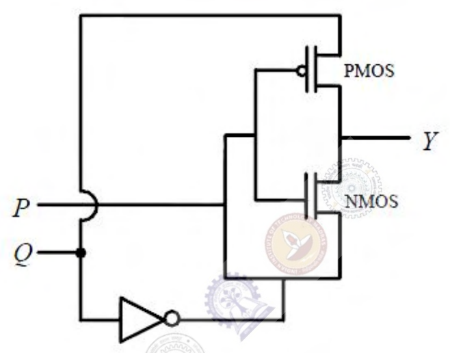
For the circuit shown, P and Q are the inputs and Y is the output. The logic implemented by the circuit is
Practise this question in The GATE Grind →
Show answer and explanation
Correct answer: MTA
Explanation
**Official disposition: marks to all (MTA).** No single option is required for grading.
If the MOS devices are treated as ideal controlled switches, P=0 connects Y through the PMOS to Q, while P=1 connects it through the NMOS to the inverted Q signal. That ideal switch table suggests XNOR.
However, the shown devices use signal-dependent rail connections; ideal Boolean switching does not establish valid full-swing output levels in every input state. The official marks-to-all decision is therefore preserved instead of forcing the idealized XNOR option as the graded answer.