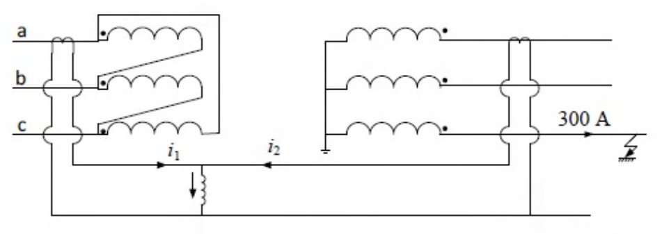
The 33/11 kV delta–star transformer and CT connections are shown. Both-side CT ratios are 500/5. For the indicated 300 A fault, the currents i1 and i2 are
The per-winding HV/LV turns ratio is 33000/(11000/√3)=3√3. A 300 A current in the faulted LV winding is therefore balanced by 300/(3√3)=100/√3 A in the associated delta winding.
The indicated HV-side CT lead consequently carries (100/√3)/100=1/√3 A, using the 500/5=100 ratio. The indicated LV CT lead i2 belongs to the unfaulted phase path in the drawing and carries zero for this single-phase fault.
Thus the pair is **1/√3 A and 0 A, A**. Current directions and the specific lead labels follow the supplied CT connection diagram.
More Principles of over-current, differential, directional and distance protection; Circuit breakers questions
GATE 2026 EE Q39– In the circuit shown, the phase currents are I A=572.812+j50.115 A I B=-254.525-j459.175 A…
GATE 2026 EE Q40– The operating characteristic of a reactance relay is given by X1\ , where X is the…
GATE 2023 EE Q20– For the three-bus power system shown in the figure, the trip signals to the circuit…
GATE 2022 EE Q13– The most commonly used relay, for the protection of an alternator against loss of…
GATE 2020 EE Q18– A lossless transmission line with 0.2 pu reactance per phase uniformly distributed along…
GATE 2019 EE Q62– In a 132 kV system, the series inductance up to the point of circuit breaker location is…