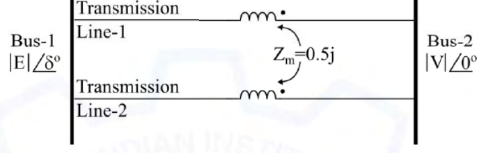
In the figure shown, self-impedances of the two transmission lines are 1.5j p.u each, and $Z_m=0.5j$ p.u is the mutual impedance. Bus voltages shown in the figure are in p.u. Given that $\delta>0$, the maximum steady-state real power that can be transferred in p.u from Bus-1 to Bus-2 is
Two coupled parallel lines carry equal currents, so each sees $Z_s+Z_m=1.5j+0.5j=2j$. The equivalent impedance is $\frac{2j}{2}=j$ p.u, and $P_{max}=\frac{|E||V|}{1}=|E||V|$.
More Series and shunt compensation, Electric field distribution and insulators, Distribution systems questions
GATE 2020 EE Q57– Bus 1 with voltage magnitude V 1=1.1 pu is sending reactive power Q 12 towards bus 2 with…
GATE 2019 EE Q59– A three-phase 50 Hz, 400 kV transmission line is 300 km long. The line inductance is 1…
GATE 2014 EE (EE1) Q24– Which property is undesirable in an electrical insulating material?
GATE 2014 EE (EE1) Q50– A 1 km resistive feeder of negligible reactance is supplied at both ends by in-phase…
GATE 2014 EE (EE2) Q26– Shunt reactors in high-voltage transmission systems are used to .
GATE 2016 EE (EE2) Q25– A lossless 400 kV, three-phase 50 Hz line has inductance 1.6 mH/km/phase and capacitance…