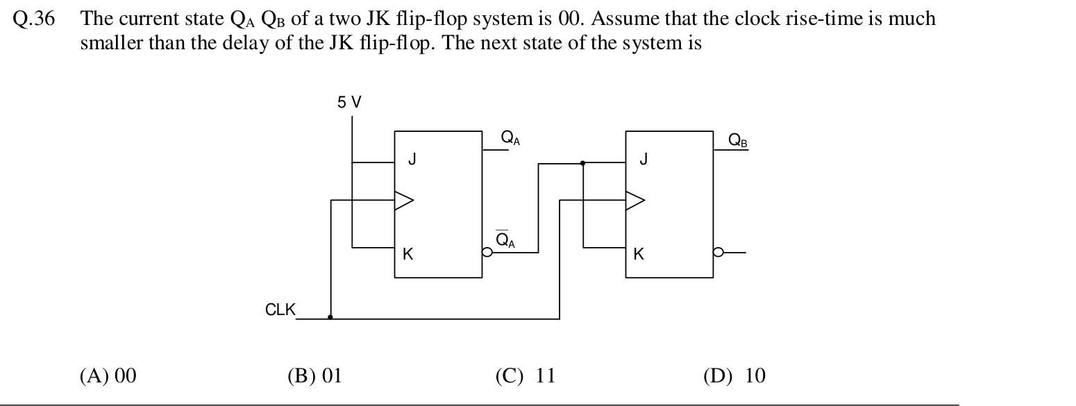
The current state $Q_A Q_B$ of a two JK flip-flop system is 00. Assume that the clock rise-time is much smaller than the delay of the JK flip-flop. The next state of the system is
Because the clock rise-time is much shorter than the flip-flop delay, both flip-flops see the old outputs at the clock edge. Flip-flop A has $J = K = 1$, so it toggles from 0 to 1. Flip-flop B has $J = K = \bar{Q}_A = 1$ (as $Q_A = 0$ before the edge), so it also toggles from 0 to 1. The next state is $Q_A Q_B = 11$.
More VCOs and timers, combinatorial and sequential logic circuits, multiplexers, demultiplexers questions
GATE 2015 EE Q25– In the 4 1 multiplexer, the output F is given by F = A B. Find the required input 'I 3 I 2…
GATE 2015 EE Q47– The figure shows a digital circuit constructed using negative edge triggered J-K flip…
GATE 2015 EE Q48– f(A, B, C, D) = M(0, 1, 3, 4, 5, 7, 9, 11, 12, 13, 14, 15) is a maxterm representation of…
GATE 2017 EE Q23– The Boolean expression AB + AC + BC simplifies to
GATE 2017 EE Q46– The output expression for the Karnaugh map shown below is AB \ CD 00 01 11 10 --- --- ---…
GATE 2017 EE Q47– The logical gate implemented using the circuit shown below where, V 1 and V 2 are inputs…