GATE 2017 EE – Question 47
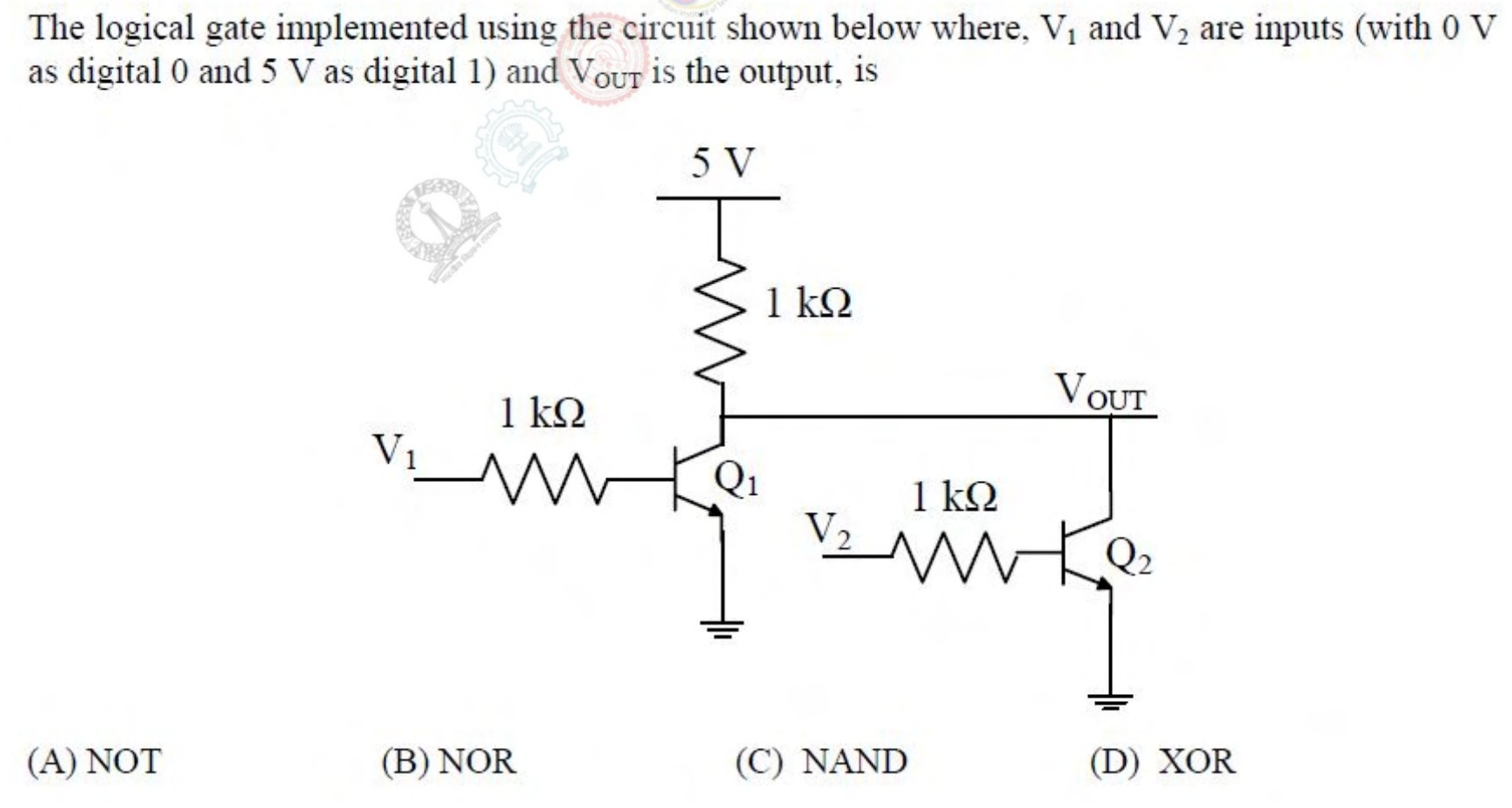
The logical gate implemented using the circuit shown below where, $V_1$ and $V_2$ are inputs (with 0 V as digital 0 and 5 V as digital 1) and $V_{OUT}$ is the output, is
Practise this question in The GATE Grind →
Show answer and explanation
Correct answer: (B) NOR
Explanation
If either input is high, its transistor turns on and pulls $V_{OUT}$ down to nearly 0 V. The output is high only when both transistors are off, which means both inputs are low. That is the NOR function.