GATE 2017 EE – Question 24
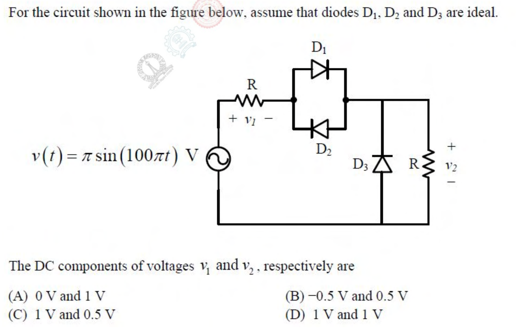
For the circuit shown in the figure below, assume that diodes $D_1$, $D_2$ and $D_3$ are ideal.
[Figure: A source $v(t) = \pi\sin(100\pi t)$ V in series with a resistor R, across which $v_1$ is measured. Next, diodes $D_1$ and $D_2$ are connected in anti-parallel. Then a diode $D_3$ is connected from the output node to ground in parallel with a second resistor R, across which $v_2$ is measured.]
The DC components of voltages $v_1$ and $v_2$, respectively are
Practise this question in The GATE Grind →
Show answer and explanation
Correct answer: (B) $-0.5$ V and 0.5 V
Explanation
Anti-parallel ideal diodes act like a short circuit for either polarity. During the positive half-cycle $D_3$ is off, so the two equal resistors form a divider and $v_1 = v_2 = \frac{v}{2}$. During the negative half-cycle $D_3$ conducts, so $v_2 = 0$ and $v_1 = v$. The average of $\pi\sin$ over its positive half-cycle, taken over the full period, is 1, so $v_1$ has a DC value of $0.5 - 1 = -0.5$ V and $v_2$ has $0.5$ V.