GATE 2015 EE (EE2) – Question 18
In the shown circuit, $V_{in}=100\sin(100\pi t)$ V and $100\pi RC=50$. Steady-state average voltage across R is nearest to
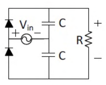
Practise this question in The GATE Grind →
Show answer and explanation
Correct answer: (C) 200 V
Explanation
The opposite diode orientations charge the two capacitors on alternate half-cycles. With ωRC=50, charge loss per cycle is small, so each capacitor holds approximately the 100 V input peak.
Their voltages add across R in this full-wave voltage-doubler arrangement. The approximate DC output is therefore 2×100=**200 V, C**, allowing a small ripple-related reduction rather than treating the output as a simple rectified average.
More Simple diode circuits: clipping, clamping, rectifiers questions
- GATE 2026 EE Q33
- GATE 2025 EE Q39
- GATE 2024 EE Q60
- GATE 2022 EE Q25
- GATE 2021 EE Q34
- GATE 2021 EE Q35
All Simple diode circuits: clipping, clamping, rectifiers questions →