GATE 2023 EC – Question 21
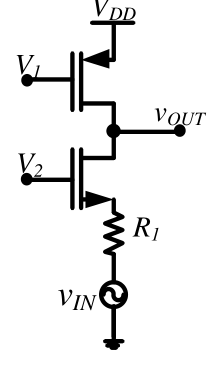
In the circuit shown below, $V_1$ and $V_2$ are bias voltages. Based on input and output impedances, the circuit behaves as a
Practise this question in The GATE Grind →
Show answer and explanation
Correct answer: (B) voltage controlled current source.
Explanation
The input voltage drives the source of the upper-gate-biased transistor through a resistor, so the input current is set by $v_{in}/(R_1+1/g_m)$: the input side is a voltage-driven, finite-impedance port. The output is taken at the drain of a common-gate stage, which has a very high output impedance and delivers a current proportional to that input current. A voltage-driven input and a high-impedance current output make it a voltage controlled current source.