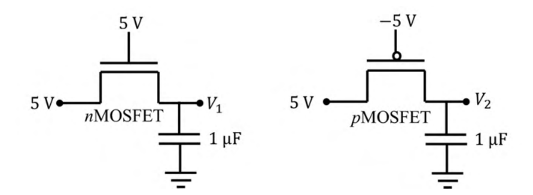
The ideal long channel nMOSFET and pMOSFET devices shown in the circuits have threshold voltages of 1 V and −1 V, respectively. The MOSFET substrates are connected to their respective sources. Ignore leakage currents and assume that the capacitors are initially discharged. For the applied voltages as shown, the steady state voltages are ________.
The nMOSFET with gate at 5 V charges its capacitor until $V_{GS}=V_T$, i.e. until $V_1=5-1=4$ V (an nMOSFET passes a weak high). The pMOSFET has its gate at $-5$ V, so $V_{SG}=5-(-5)=10$ V stays well above 1 V while the capacitor charges to the full 5 V (a pMOSFET passes a strong high), so $V_2=5$ V.
More BJT and MOSFET Amplifiers questions
GATE 2022 EC Q40– Consider an ideal long channel nMOSFET (enhancement-mode) with gate length 10\ m and width…
GATE 2022 EC Q59– Consider the circuit shown with an ideal long channel nMOSFET (enhancement-mode, substrate…
GATE 2021 EC Q18– In the circuit shown in the figure, the transistors M 1 and M 2 are operating in…
GATE 2021 EC Q54– For the transistor M 1 in the circuit shown in the figure, nC ox=100\ A/V2 and (W/L)=10,…
GATE 2020 EC Q45– For the BJT in the amplifier shown below, V BE=0.7 V, kT/q=26 mV. Assume that BJT output…
GATE 2020 EC Q46– An enhancement MOSFET of threshold voltage 3 V is being used in the sample and hold…