GATE 2022 EC – Question 18
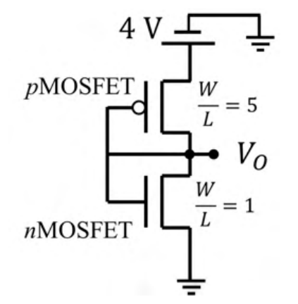
Consider the CMOS circuit shown in the figure (substrates are connected to their respective sources). The gate width ($W$) to gate length ($L$) ratios $\left(\frac WL\right)$ of the transistors are as shown. Both the transistors have the same gate oxide capacitance per unit area. For the pMOSFET, the threshold voltage is $-1$ V and the mobility of holes is $40\ \frac{\text{cm}^2}{\text{V.s}}$. For the nMOSFET, the threshold voltage is 1 V and the mobility of electrons is $300\ \frac{\text{cm}^2}{\text{V.s}}$. The steady state output voltage $V_o$ is ________.
Practise this question in The GATE Grind →
Show answer and explanation
Correct answer: (C) less than 2 V
Explanation
Both gates are tied to the output, so each transistor is diode-connected and saturated. The current factors are $\mu_pC_{ox}\frac WL=40\times5=200$ for the pMOSFET and $\mu_nC_{ox}\frac WL=300\times1=300$ for the nMOSFET (in the same units). Equating currents: $200(4-V_o-1)^2=300(V_o-1)^2$, so $0.816(3-V_o)=V_o-1$, giving $V_o\approx1.9$ V, which is less than 2 V. Both devices are indeed in saturation at this point.