GATE 2023 EC – Question 23
Digital Circuits · Combinatorial Circuits · 1 mark · Multiple choice
In the circuit shown below, P and Q are the inputs. The logical function realized by the circuit shown below is
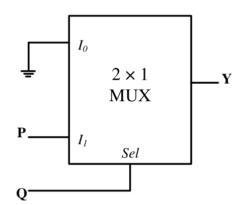
- $Y=PQ$
- $Y=P+Q$
- $Y=\overline{PQ}$
- $Y=\overline{P+Q}$
Practise this question in The GATE Grind →
Show answer and explanation
Correct answer: (A) $Y=PQ$
Explanation
The 2:1 MUX picks $I_0$ when $Q=0$ and $I_1$ when $Q=1$. Here $I_0=0$ and $I_1=P$, so $Y=\bar Q\cdot0+Q\cdot P=PQ$, an AND gate.
More Combinatorial Circuits questions
- GATE 2022 EC Q19 – Consider the 2-bit multiplexer (MUX) shown in the figure. For OUTPUT to be the XOR of C…
- GATE 2022 EC Q27 – Select the Boolean function(s) equivalent to x+yz, where x, y, and z are Boolean…
- GATE 2022 EC Q28 – Select the correct statement(s) regarding CMOS implementation of NOT gates.
- GATE 2022 EC Q49 – Consider a Boolean gate (D) where the output Y is related to the inputs A and B as, Y=A+…
- GATE 2021 EC Q41 – The propagation delays of the XOR gate, AND gate and multiplexer (MUX) in the circuit…
- GATE 2020 EC Q20 – The figure below shows a multiplexer where S 1 and S 0 are the select lines, I 0 to I 3…
All Combinatorial Circuits questions →