GATE 2026 EE – Question 28
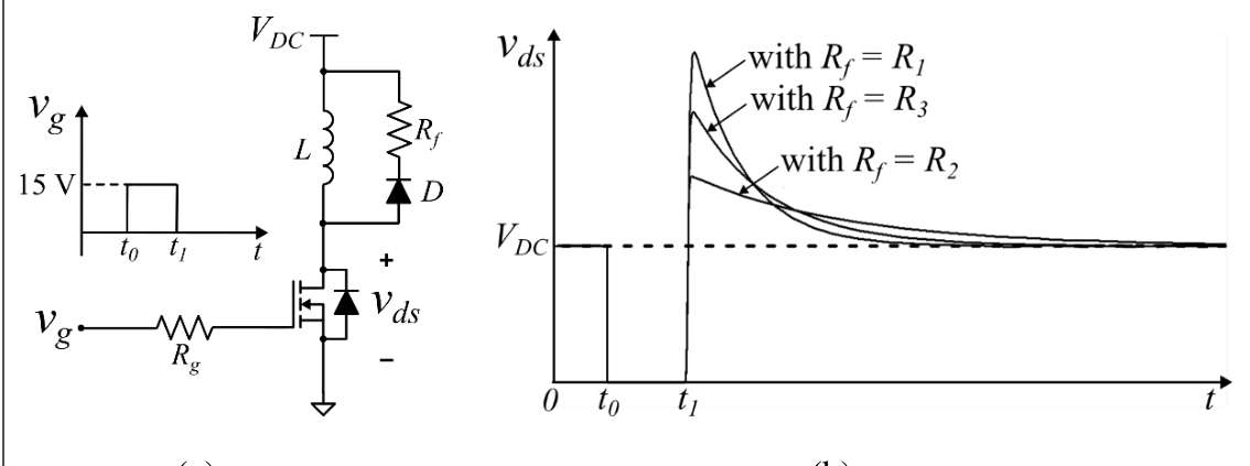
Consider the circuit shown in Figure (a). A gate pulse $v_g$ is applied between time instants $t_0$ and $t_1$. After $t_1$, during the MOSFET turn OFF process, it experiences a voltage overshoot.
Based on the $v_{ds}$ waveforms shown in Figure (b), which one of the following options is correct?
Practise this question in The GATE Grind →
Show answer and explanation
Correct answer: (B) $R_1>R_3>R_2$
Explanation
The voltage overshoot at turn-off grows with the resistance $R_f$ of the freewheeling path: the larger the resistance, the larger the peak of $v_{ds}$. In Figure (b) the curve labelled $R_1$ has the highest peak, then $R_3$, then $R_2$. So $R_1>R_3>R_2$.