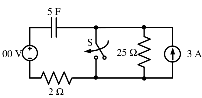
**Before t = 0** (switch open, DC steady state) the capacitor carries no current, so the loop with the 100 V source and the $2\ \Omega$ resistor has no drop. The 3 A source pushes all its current through the $25\ \Omega$ resistor, so the node after the capacitor sits at $3\times25=75$ V. The capacitor therefore starts at $v_c(0)=100-75=25$ V.
**After t = 0** the closed switch short-circuits the $25\ \Omega$ resistor and the 3 A source. The capacitor charges through $2\ \Omega$ towards 100 V with $\tau=RC=2\times5=10$ s:
$v_c(t)=100-75e^{-t/10}$.
Setting $v_c=50$ V gives $e^{-t/10}=\tfrac{2}{3}$, so $t=10\ln1.5\approx4.05$ s.
More Transient response of DC and AC networks, sinusoidal steady-state analysis, resonance, two port networks, balanced three phase circuits, star-delta transformation, complex power and power factor in AC circuits questions
GATE 2024 EE Q14– The circuit shown in the figure with the switch S open, is in steady state. After the…
GATE 2023 EE Q29– The value of parameters of the circuit shown in the figure are R 1=2\ , R 2=2\ , R 3=3\ ,…
GATE 2023 EE Q54– The circuit shown in the figure is initially in the steady state with the switch K in open…
GATE 2022 EE Q21– In the circuit shown below, a three-phase star-connected unbalanced load is connected to a…
GATE 2022 EE Q27– An inductor having a Q-factor of 60 is connected in series with a capacitor having a…
GATE 2022 EE Q28– The network shown below has a resonant frequency of 150 kHz and a bandwidth of 600 Hz. The…