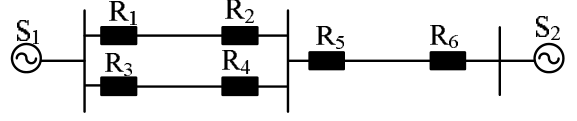
The shown two-generator system has six overcurrent relays R1–R6, using an appropriate mix of directional and nondirectional relays. The remote backup relays for R4 are
R4 protects the lower left parallel line from the middle bus. If it fails to clear a fault on that line, current can arrive at that bus from both remote source paths.
From S1 the path uses the upper parallel line, whose remote source-end relay is R1. From S2 the source-end relay on the right line is R6. Both must remove their respective feeds to back up the failed R4.
Thus the remote backup pair is **R1 and R6, D**.
More Principles of over-current, differential, directional and distance protection; Circuit breakers questions
GATE 2015 EE (EE2) Q52– The 33/11 kV delta–star transformer and CT connections are shown. Both-side CT ratios are…
GATE 2026 EE Q39– In the circuit shown, the phase currents are I A=572.812+j50.115 A I B=-254.525-j459.175 A…
GATE 2026 EE Q40– The operating characteristic of a reactance relay is given by X1\ , where X is the…
GATE 2023 EE Q20– For the three-bus power system shown in the figure, the trip signals to the circuit…
GATE 2022 EE Q13– The most commonly used relay, for the protection of an alternator against loss of…
GATE 2020 EE Q18– A lossless transmission line with 0.2 pu reactance per phase uniformly distributed along…