GATE 2018 EE – Question 39
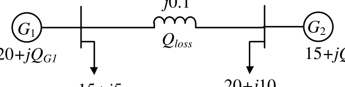
Consider the two bus power system network with given loads as shown in the figure. All the values shown in the figure are in per unit. The reactive power supplied by generator $G_1$ and $G_2$ are $Q_{G1}$ and $Q_{G2}$ respectively. The per unit values of $Q_{G1}$, $Q_{G2}$, and line reactive power loss ($Q_{loss}$) respectively are
Practise this question in The GATE Grind →
Show answer and explanation
Correct answer: (C) 6.34, 11.34, 2.68
Explanation
Bus 1 has $20$ pu generation and $15$ pu load, so $P_{12}=5=\frac{\sin\delta}{0.1}$ and $\delta=30^\circ$. The reactive flows are $Q_{12}=\frac{1-\cos30^\circ}{0.1}=1.34$ at each end, going out of each bus into the line. Then $Q_{G1}=5+1.34=6.34$, $Q_{G2}=10+1.34=11.34$ and $Q_{loss}=2\times1.34=2.68$.