Home › Previous year questions › GATE 2026 EC › Question 17GATE 2026 EC – Question 17 Analog Circuits · Op-amp Circuits · 1 mark · Multiple choice
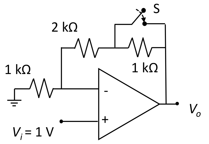
The ideal OP-AMP circuit shown in the Figure produces output voltage $V_o = x$ when the Switch, S, is open. Which of the options represents the output voltage when S is closed?
$x$ $\frac23 x$ $\frac34 x$ $\frac12 x$ Practise this question in The GATE Grind →
Show answer and explanation Correct answer: (C) $\frac34 x$
Explanation This is a non-inverting amplifier with gain $1+\dfrac{R_f}{R_g}$, where $R_g=1\ \text{k}\Omega$.
Switch open: $R_f=2\text{ k}+1\text{ k}=3$ k$\Omega$, gain $=4$, so $x=4V_i=4$ V. Switch closed: it shorts the $1\ \text{k}\Omega$, so $R_f=2$ k$\Omega$, gain $=3$, $V_o=3$ V. $\dfrac{V_o}x=\dfrac34$, so $V_o=\dfrac34x$.
More Op-amp Circuits questions GATE 2026 EC Q53 – A circuit using an ideal OP-AMP is shown in the Figure. Which of the following options… GATE 2026 EC Q62 – Consider an ideal OP-AMP circuit as shown in the Figure. The resistances R 1=R 2=R 3=R… GATE 2025 EC Q29 – Which of the following statements is/are TRUE with respect to an ideal opamp? GATE 2025 EC Q34 – All the components in the bandpass filter given below are ideal. The lower -3 dB frequency… GATE 2024 EC Q49 – The opamps in the circuit shown are ideal, but have saturation voltages of 10 V. Assume… GATE 2024 EC Q50 – In the circuit below, the opamp is ideal. If the circuit is to show sustained… All Op-amp Circuits questions →