GATE 2025 EE – Question 38
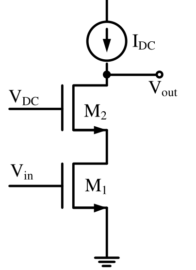
In the circuit, $I_{DC}$ is an ideal current source. The transistors $M_1$ and $M_2$ are assumed to be biased in saturation, wherein $V_{in}$ is the input signal and $V_{DC}$ is DC voltage. Both transistors have a small signal resistance of $r_{ds}$ and trans-conductance of $g_m$. The small signal output impedance of this circuit is
Practise this question in The GATE Grind →
Show answer and explanation
Correct answer: (C) $g_mr_{ds}^2+2r_{ds}$
Explanation
$M_1$ (gate at $V_{in}$, small-signal ground) is the driver and $M_2$ (gate at the DC voltage) is the cascode device on top, so the output impedance is that of a cascode: $R_{out}=r_{ds1}+r_{ds2}+g_{m2}r_{ds1}r_{ds2}=2r_{ds}+g_mr_{ds}^2$. The ideal current source above the output has infinite impedance and adds nothing.