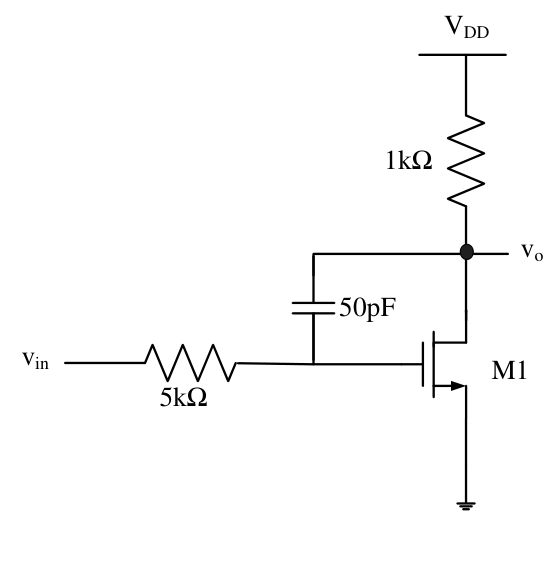
M1 in the shown circuit is saturated with $g_m=0.01$ S. Ignore internal parasitic capacitances and set channel-length modulation to zero. The small-signal input pole frequency in kHz is ________.
The low-frequency common-source gain is $-g_mR_D=-10$. Miller multiplication makes the input capacitance approximately $50(1-(-10))=550$ pF. With 5 kΩ source resistance this gives $f_p\approx1/[2\pi(5000)(550\mathrm{\ pF})]=57.87$ kHz.
An exact two-node calculation with the sole feedback capacitor gives time constant $C(R_S+R_D+g_mR_SR_D)=2.8$ μs, or **56.84 kHz**. Both agree with the official interval 56–63 kHz; the latter includes the output-node loading exactly.
More BJT and MOSFET Amplifiers questions
GATE 2026 EC Q18– Consider the circuit shown in the Figure with V i = 3 V and V CC = 12 V. Assume V BE=0.7 V…
GATE 2026 EC Q50– A small signal source, V i(t)=A(105t)+B(107t) is applied to a BJT circuit as shown in the…
GATE 2026 EC Q60– An n-channel MOSFET is connected as shown in the Figure. Assume V TH=1 V, V DD=5 V, and C…
GATE 2025 EC Q21– A simplified small-signal equivalent circuit of a BJT-based amplifier is given below. The…
GATE 2025 EC Q22– The ideal BJT in the circuit given below is biased in the active region with a of 100. If…
GATE 2025 EC Q30– Which of the following statements is/are TRUE with respect to ideal MOSFET-based…