GATE 2018 EE – Question 63
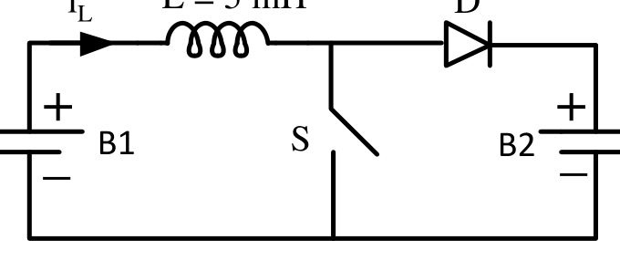
A dc to dc converter shown in the figure is charging a battery bank, B2 whose voltage is constant at 150 V. B1 is another battery bank whose voltage is constant at 50 V. The value of the inductor, L is 5 mH and the ideal switch, S is operated with a switching frequency of 5 kHz with a duty ratio of 0.4. Once the circuit has attained steady state and assuming the diode D to be ideal, the power transferred from B1 to B2 (in Watt) is ________ (up to 2 decimal places).
Practise this question in The GATE Grind →
Show answer and explanation
Correct answer: 12
Explanation
The period is $200\ \mu$s and the on-time is $80\ \mu$s, so the inductor current peaks at $\frac{50\times80\ \mu\text{s}}{5\text{ mH}}=0.8$ A. The discharge against $150-50=100$ V takes $\frac{5\text{ mH}\times0.8}{100}=40\ \mu$s, which is less than the remaining off time, so the converter is in discontinuous mode. The average current is $\frac12\times0.8\times\frac{80+40}{200}=0.24$ A, and the power drawn from B1 is $50\times0.24=12$ W.