GATE 2016 EE – Question 32
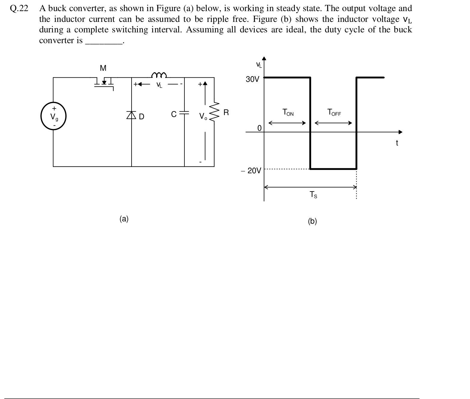
A buck converter, as shown in Figure (a) below, is working in steady state. The output voltage and the inductor current can be assumed to be ripple free. Figure (b) shows the inductor voltage $v_L$ during a complete switching interval. Assuming all devices are ideal, the duty cycle of the buck converter is ________.
[Figure (a): A buck converter with input $V_g$, switch M, diode D, inductor L, capacitor C and load R. Figure (b): The inductor voltage $v_L$ is +30 V during $T_{ON}$ and -20 V during $T_{OFF}$, over a switching period $T_S$.]
Practise this question in The GATE Grind →
Show answer and explanation
Correct answer: 0.39 to 0.41
Explanation
In steady state the average inductor voltage over a period is zero, so the volt-seconds balance: $30 \, T_{ON} = 20 \, T_{OFF}$. Hence $\frac{T_{ON}}{T_{OFF}} = \frac{2}{3}$ and the duty cycle is $D = \frac{T_{ON}}{T_{ON} + T_{OFF}} = \frac{2}{5} = 0.4$.