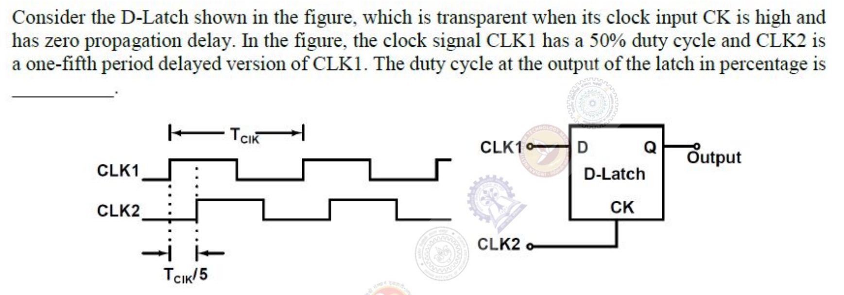
Consider the D-Latch shown in the figure, which is transparent when its clock input CK is high and has zero propagation delay. In the figure, the clock signal CLK1 has a 50% duty cycle and CLK2 is a one-fifth period delayed version of CLK1. The duty cycle at the output of the latch in percentage is ________.
Take one period $T$. CLK1 is high from 0 to $0.5T$, and CLK2 is high from $0.2T$ to $0.7T$. The latch follows D only while CLK2 is high. During that time D is high from $0.2T$ to $0.5T$ and low from $0.5T$ to $0.7T$, so the output goes high at $0.2T$ and falls at $0.5T$. After $0.7T$ the latch holds the value 0 until $1.2T$. So the output is high for $0.3T$ of each period, a duty cycle of 30%.
More Sequential Circuits questions
GATE 2017 EC Q54– A 4-bit shift register circuit configured for right-shift operation, i.e. D in A, A B, B…
GATE 2017 EC Q56– A finite state machine (FSM) is implemented using the D flip-flops A and B, and logic…
GATE 2014 EC (EC1) Q26– Five JK flip-flops are cascaded as shown. Applied clock frequency is 1 MHz. Find the…
GATE 2014 EC (EC1) Q52– The logic circuit realizes the shown state diagram when Q₁ connects to XOR input A. If XOR…
GATE 2014 EC (EC2) Q50– For the circuit shown, select the output y timing diagram from W1,W2,W3,W4.
GATE 2014 EC (EC2) Q51– Both flip-flop outputs Q₁,Q₂ start at 0. Find the sequence generated at Q₁ by the clock.