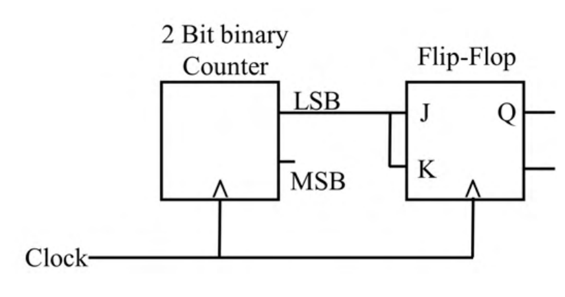
Correct answer: (A) frequency is $f_0/4$ and duty cycle is 50%
Explanation
The J and K inputs are both connected to the counter's LSB, so the flip-flop toggles when LSB $=1$ and holds when LSB $=0$. The LSB alternates $0,1,0,1,\dots$, so Q toggles on every second clock edge. Q therefore has a period of four clock cycles (frequency $f_0/4$) and is high for two of them (50% duty cycle).
More Sequential Circuits questions
GATE 2021 EC Q56– The propagation delay of the exclusive-OR (XOR) gate in the circuit in the figure is 3 ns.…
GATE 2020 EC Q49– The state diagram of a sequence detector is shown below. State S 0 is the initial state of…
GATE 2020 EC Q60– For the components in the sequential circuit shown below, t pd is the propagation delay, t…
GATE 2019 EC Q35– In the circuit shown, the clock frequency, i.e., the frequency of the Clk signal, is 12…
GATE 2019 EC Q49– The state transition diagram for the circuit shown is
GATE 2018 EC Q29– A traffic signal cycles from GREEN to YELLOW, YELLOW to RED and RED to GREEN. In each…