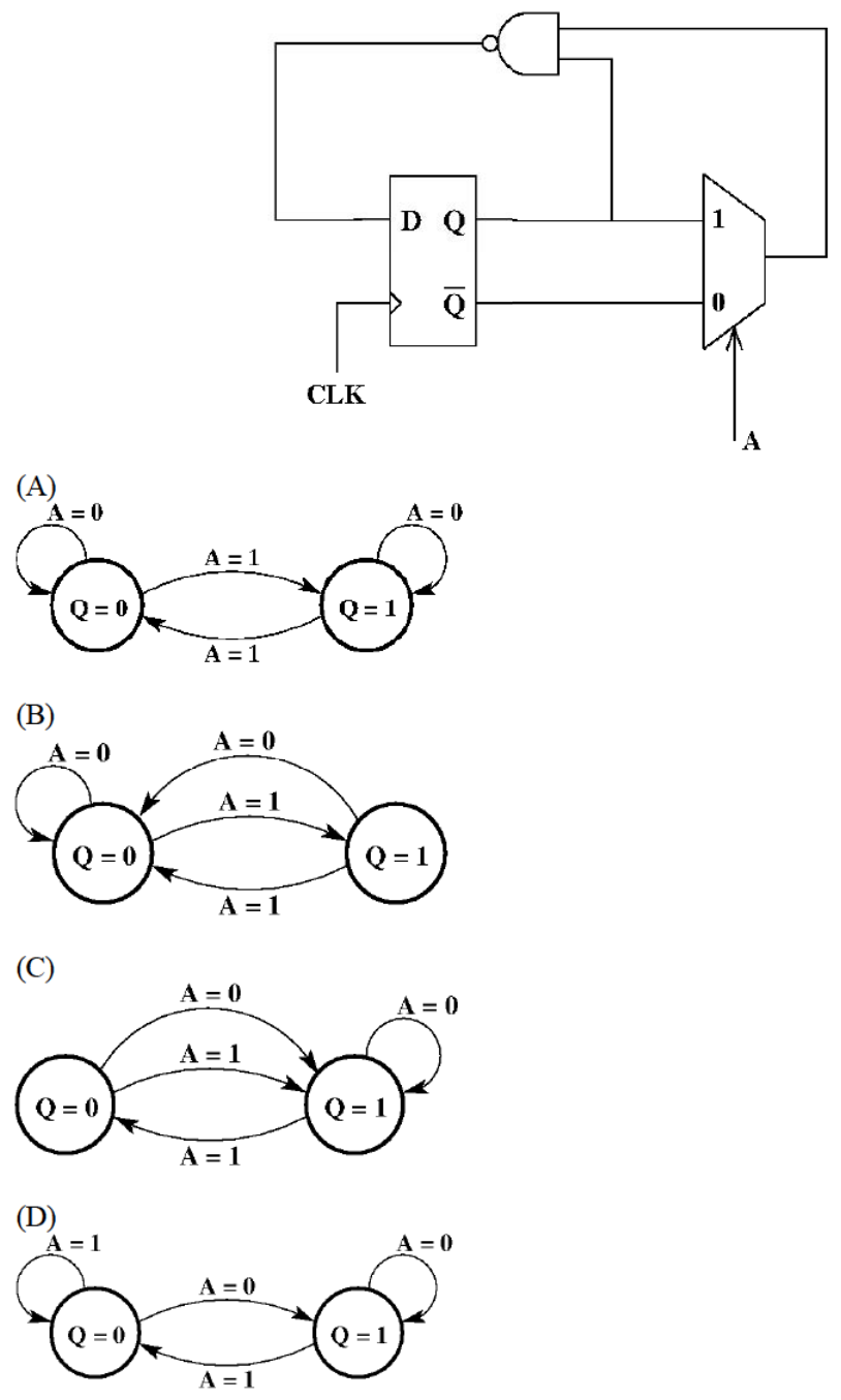
Let $M$ be the multiplexer output. With $A=1$ it passes $Q$ (input 1) and with $A=0$ it passes $\bar Q$ (input 0). The flip-flop input is $D=\overline{M\cdot Q}$, the NAND of $M$ and $Q$.
$A=1$: $M=Q$, so $D=\overline{Q\cdot Q}=\bar Q$ and the flip-flop toggles: $0\to1$ and $1\to0$.
$A=0$: $M=\bar Q$, so $D=\overline{\bar Q\cdot Q}=1$ and the next state is 1 whatever $Q$ was: $0\to1$ and $1\to1$ (a self-loop).
This is diagram (C).
More Sequential Circuits questions
GATE 2018 EC Q29– A traffic signal cycles from GREEN to YELLOW, YELLOW to RED and RED to GREEN. In each…
GATE 2018 EC Q56– In the circuit shown below, a positive edge-triggered D Flip-Flop is used for sampling…
GATE 2017 EC Q25– In the latch circuit shown, the NAND gates have non-zero, but unequal propagation delays.…
GATE 2017 EC Q27– Consider the D-Latch shown in the figure, which is transparent when its clock input CK is…
GATE 2017 EC Q54– A 4-bit shift register circuit configured for right-shift operation, i.e. D in A, A B, B…
GATE 2017 EC Q56– A finite state machine (FSM) is implemented using the D flip-flops A and B, and logic…