GATE 2022 EC – Question 54
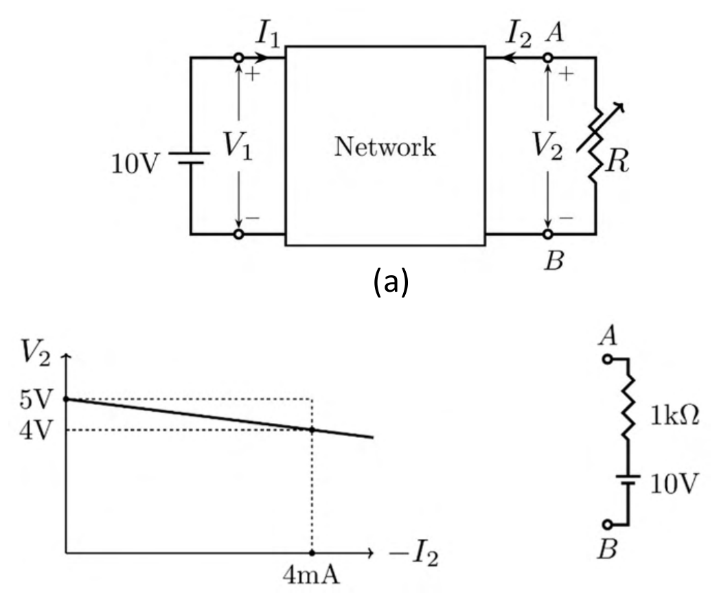
A linear 2-port network is shown in Fig. (a). An ideal DC voltage source of 10 V is connected across Port 1. A variable resistance $R$ is connected across Port 2. As $R$ is varied, the measured voltage and current at Port 2 is shown in Fig. (b) as a $V_2$ versus $-I_2$ plot. Note that for $V_2=5$ V, $I_2=0$ mA, and for $V_2=4$ V, $I_2=-4$ mA.
When the variable resistance $R$ at Port 2 is replaced by the load shown in Fig. (c), the current $I_2$ is ________ mA (rounded off to one decimal place).
Practise this question in The GATE Grind →
Show answer and explanation
Correct answer: 4
Explanation
Seen from Port 2, the network is a Thevenin source: $V_{th}=5$ V (the open-circuit voltage) and $R_{th}=\frac{5-4}{4\text{ mA}}=250\ \Omega$, so $V_2=5-250(-I_2)$. The load in Fig. (c) is a $1\ \text{k}\Omega$ resistor in series with a 10 V source with its positive terminal at A, so the current leaving Port 2 is $-I_2=\frac{V_2-10}{1\text{k}}$. Substituting, $V_2=5-0.25(V_2-10)$ gives $V_2=6$ V, so $-I_2=-4$ mA and $I_2=+4.0$ mA.