GATE 2025 EC – Question 45
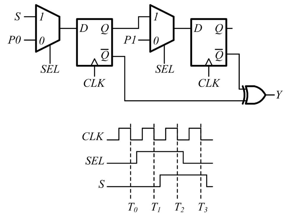
A positive-edge-triggered sequential circuit is shown below. There are no timing violations in the circuit. Input $P0$ is set to logic ‘0’ and $P1$ is set to logic ‘1’ at all times. The timing diagram of the inputs $SEL$ and $S$ are also shown below.
The sequence of output $Y$ from time $T_0$ to $T_3$ is ________.
Practise this question in The GATE Grind →
Show answer and explanation
Correct answer: (A) 1011
Explanation
$Y=\bar Q_1\oplus\bar Q_2$. On each rising clock edge: FF1 loads $S$ if $SEL=1$ else $P0=0$; FF2 loads $Q_1$ (old value) if $SEL=1$ else $P1=1$. The rising edge before $T_0$ has $SEL=0$: $Q_1=0,\ Q_2=1$, so $Y=1\oplus0=1$. The next edge has $SEL=1,\ S=0$: $Q_1=0$, $Q_2=$ old $Q_1=0$, so $Y=1\oplus1=0$. The next edge has $SEL=1,\ S=1$: $Q_1=1$, $Q_2=0$, so $Y=0\oplus1=1$. The next has $SEL=0$: $Q_1=0,\ Q_2=1$, so $Y=1\oplus0=1$. Sequence: 1, 0, 1, 1.