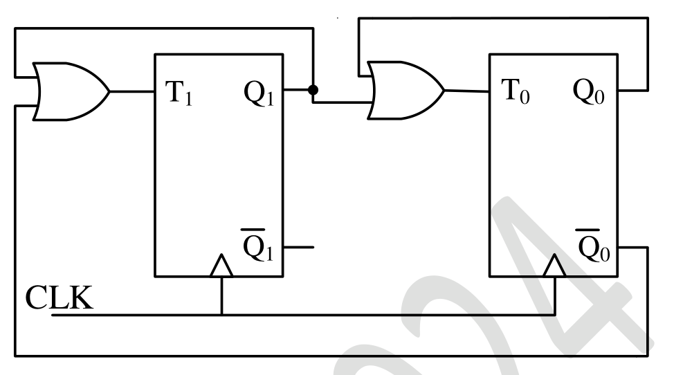
From the figure, $T_1=Q_1+\overline{Q_0}$ and $T_0=Q_1+Q_0$; a T flip-flop toggles when its input is 1. State 00: $T_1=1,T_0=0\Rightarrow10$. State 10: $T_1=1,T_0=1\Rightarrow01$. State 01: $T_1=0,T_0=1\Rightarrow00$. State 11: $T_1=1,T_0=1\Rightarrow00$. So the sequence is $11\to00\to10\to01\to00$.
More Sequential Circuits questions
GATE 2023 EC Q24– The synchronous sequential circuit shown below works at a clock frequency of 1 GHz. The…
GATE 2023 EC Q34– For the circuit shown below, the propagation delay of each NAND gate is 1 ns. The critical…
GATE 2023 EC Q63– In a given sequential circuit, initial states are Q 1=1 and Q 2=0. For a clock frequency…
GATE 2022 EC Q43– For the circuit shown, the clock frequency is f 0 and the duty cycle is 25%. For the…
GATE 2021 EC Q56– The propagation delay of the exclusive-OR (XOR) gate in the circuit in the figure is 3 ns.…
GATE 2020 EC Q49– The state diagram of a sequence detector is shown below. State S 0 is the initial state of…